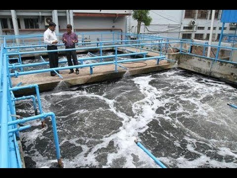
Working Procedure Of Effluent Treatment Plant:
Step-01: When Bar Screening Sensor Gate Sense Due To Flow Water
In Drain, Bar Screening Motor Will On For Cleaning
Water And Motor Will Continue
Running To Clean Drain Water.
Minimum Runing Time 2 Minutes
In Single Sense.
Step-02: There Are Two Lifting
Pump To Drain Lifting Tank. Lifting Pump Will On In Alternating Logic, When Lifting
Tank Will Full By Water,
This Two Motor Start Automatically For 8 Minutes. After 8
Minutes Two Pumps Will Operate In Alternating Logics.
Alternating Time
Could Changeable By Operator. Time Setting Function Is In Time Setting Page Of
Hmi. Lifting Tank Water Level Is High Or Not It Will Show In HMI Sensor Status Page. We Can Also Monitoring Inlet Flow Rate In Hmi. When Water Level Is Low Than Lifting Tank Pump Will Stop Automatically. If There In Flow Water In Tank Pump Will Ready After 10 Minutes.
Step-03:
There Is Low Level Detection Sensor And Two Pump In Equalization Tank. The
Sensor For Low Level Detection. If The Water Level Is Up Of Low-Level Sensor, Two Pump Of Equalization Tank Will Operate
On Alternating Method Also Flash Mixer 1 & 2 Will Rum With Pumps
Equalization Tank. Alternating Time Could Changeable By Operator As Well
As The Operator Can Change The Flow Rate Of Pump Throw The VFD Speed Setting As His/Her Wishes.
When Water Level Is Low Than Low Level Sensor Get Sense And Pump Of
Equalization Tank Will Stop. After One (01) Minute Pump Will Start Again. All
Pump On/Off & Level Sensor Status Show In
HMI Page. Remember That If The Equalization Tank Level Is Low Flash
Mixer Motor (Agitator) Will Stop Automatically, Also Notable That Equalization
Level Is Low Or MGF Tank Level Is
High Or Pac Level Is Low Than Equalization Process Will Stop Automatically.
Remember That There Are Two Equalization Blower Motor 1 & 2, If We Start Effluent Treatment Plant Start In
Auto Mode These Two Blowers Will In Alternating Logics. Alternating Time Could
Changeable By Operator. Operator Can Hold The Running
Blower. Operator Can Hold This Running Blower By Pressing
The Hold Button On HMIStatus
Page.
Step-04: Chemical Mixing 1&2
Have To Operate
By Manual Switch.
But On/Off Status
Of Mixer Motor Will Show In The HMI
Step-05:
There Are Two Doing Pump To Drain Pac Tank. Pac Pump Will On In Alternating
Logic Until Pac Tank Solution Level Is Up Of Low-Level But Must Have To Run Equalization Tank Pumps. When Solution Level
Is Low Than Pac Pump Will Stop Automatically, After 5 Sec Pump Get Ready To Run, If Pac Tank Solution Level
Is High Of Low-Level Sensor,
Notable That Pac Will Stop Automatically With Equalization Tank Pumps. Also
HCL, Lime/Naoh, Polymer Pump Will Run With Pac Pump. HCL Lime/ Naoh, Polymer Pump Runing Until Low Level
Sensor Gate Sense. When Pac And HCL Level Is Low Than Warning Siren Start
Automatically And Low-Level Alarm Signal Blink In HMI
Status Page. Alarm Could Stop By Press Acknowledge Button.
Step-06:
There Is One Ph Sensor In Biological Tank, Ph Value Is Shown At Home Page
Of Hmi. Auto Acid Dosing Pump Will On When Ph Value Is Low Than The Set Ph Value And Pump Will Stop When Ph Value Is High Than The Set Value. Ph Value Have To Set In Ph Meter By Operator. But Notable That Auto Acid Dosing Will Not Run In Equalization Process Stop Condition.
Step-07:
There Are Two Blowers In Biological Tank. Two Blowers Of Biological Tank
Will Operate On Alternating Method. Alternating Time Could Changeable By Operator.
The Operator Can Change The Speed Of Blowers Throw The Vfd Speed Setting.
Motor Speed Will Change Depend On Do Analyzer Meter Reading. Operator
Monitor Do Read In Hmi Home
Page And Do Control Page.
Step-09: There Are Two Pumps In AST Tank. Two Pump Of AST Tank Will Operate
On Alternating Method.
Alternating Time Could Changeable By Operator. The Operator Can Change The Flow Rate Of
Pump Throw The VFD Speed Setting As His/Her
Wishes. These Two Pump Will Start In Auto Starting
Period.
Step-10: There
Are Two Level Detection Sensor
And Two Pump In Mgf Tank. One Sensor For Low Level And Another
For High Level Detection. Two Pump Of MGF Tank Will
Operate On Alternating Method. Alternating Time Could Changeable By Operator As
Well As The Operator Can Change The Flow Rate Of Pump Throw The VFD Speed Setting As His/Her Wishes. When
Level Will Be Low Both Of Pump Will Stop, When Water Level Will Up The
Low-Level Sensor For 20 Minutes Than MGF Pump
Will Start. Outlet
Flow Meter Show Flow Rate In HMI Home
Page And Tertiary Treatment
Page.